ENGINE EXHAUST POWER GENERATION
HT1100A-MTFM (HT593C-A-MTFM)
INTRODUCTION
Shannon design HT1100A-MTFM is specific to a Petro Chemical Process High Temperature Environment, a non-wicking Design. Conditions are severe and problematic but most important, this design is non-porous at high temperature, producing a self-contained insulation system that is still removable and re-usable. Conditions of hot oil, hydrocarbon, chemical and most acidic and basic environments while at the same time, generating acoustic performance targets to meet the standard.
Shannon Acoustic Blanket Applications include: Steam Turbines, Gas Turbines, Exhaust Ducting, Exhaust Piping, Diffusers, Process Pumps, Turbines, Vessels, Heat Exchangers, Process Piping, Flanges, Fittings, Equipment & Equipment Heads.
This design is a Thermal/Acoustic Noise Reduction Barrier with a service temperature to 1100˚F (593˚C).
Acoustic Performance
4 – 15 dBA Reduction Overall
Finished Surface Mass
1.7lb/ft² (8.3kg/m²) to 3.7lb/ft² (18.1kg/m²)
Blanket Components
The Outer Jacketing consists of a layer of Stainless Steel Type 304 Knitted Wire Mesh .011” Dia. @ 16ft²/LB (0.28 mm Dia. @ 3.3 m²/kg) and a layer an Outer Jacketing of 16.5oz/yd² (560g/m²) PTFE Teflon® Impregnated Fiberglass Cloth and Mass Loaded Vinyl “Reflector” – 1.0lb/ft² (4.9kg/m²)-2.0lb/ft² (9.8kg/m²). The inner jacketing consists of a layer of Stainless Steel Type 304 Sheet Foil .002” (.05mm) thickness and a layer of Stainless Steel Knitted Wire Mesh. The Insulation Core Material is an 11 lb/ft³ (176.2 kg/m³) Fiberglass Needled Mat-Type E Fiber and will act as an “Absorber” of noise energy. The Fiberglass Mat is encapsulated by the inner and outer layers of jacketing, then stapled together, producing a Self Contained Blanket System. The Blanket System includes an Integral Fastener for install & removal. The combination of reflection and absorption will generate given expectations of noise reduction with varying surface mass and varying blanket thickness.

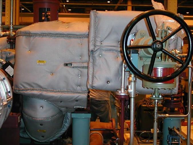
Steam Inlet T&T Valve to Steam Turbine
BLANKET THICKNESS SURFACE TEMPERATURE REFERENCE
Operating Temp |
Thickness |
Surface Temp |
Thickness |
Surface Temp |
Thickness |
Surface Temp |
|---|---|---|---|---|---|---|
| 371˚ C (700˚ F) | 40 mm (1.5″) | 69.2˚ C (156.5˚ F) | 50 mm (2″) | 59.8˚ C (139.6˚ F) | 65 mm (2.5″) | 53.6˚ C (128.4˚ F) |
| 427˚ C (800˚ F) | 40 mm (1.5″) | 79.2˚ C (174.6˚ F) | 50 mm (2″) | 68.1˚ C (154.5˚ F) | 65 mm (2.5″) | 60.7˚ C (141.2˚ F) |
| 482˚ C (900˚ F) | 40 mm (1.5″) | 90.3˚ C (194.5˚ F ) | 50 mm (2″) | 77.2˚ C (171.0˚ F ) | 65 mm (2.5″) | 68.6˚ C (155.4˚ F ) |
| 538˚ C (1000˚ F) | 50 mm (2″) | 87.4˚ C (189.4˚ F) | 65 mm (2.5″) | 77.3˚ C (171.2˚ F) | 80 mm (3″) | 70.1˚ C (158.1˚ F) |
| 593˚ C (1100˚ F) | 50 mm (2″) | 98.7˚ C (209.7˚ F) | 65 mm (2.5″) | 87.1˚ C (188.8˚ F) | 80 mm (3″) | 78.7˚ C (173.7˚ F) |
* The above referenced Cold Face Surface Temperatures should be used as guidelines for blanket insulation thickness design.
* The Cold Face Surface Temperature of the blanket should approach surrounding ambient temperature conditions.
* The economic thickness of the blanket should consider blanket cost, thermal performance and blanket design constraints.
* Heat loss calculations are based on a 21.1˚ C (70˚ F) ambient temperature using a flat surface condition.
THICKNESS |
SURFACE MASS |
Noise Reduction Range |
|---|---|---|
| 1” (2.5CM) | 1.8 lb/ft² to 2.8 lb/ ft² (8.8-13.7kg/m²) | 1.5 DBA to 6 DBA Reduction |
| 1 ½” (3.8CM) | 2.2 lb/ ft² to 3.2 lb/ ft² (10.7-15.6kg/m²) | 4 DBA to 8 DBA Reduction |
| 2” (5CM) | 2.6 lb/ ft² to 3.6 lb/ ft² (12.7-17.6kg/m²) | 5 DBA to 10 DBA Reduction |
| 2 ½” (6.4CM) | 3.0 lb/ ft² to 4.0 lb/ ft² (14.7-19.5kg/m²) | 7 DBA to 13 DBA Reduction |
